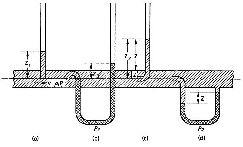
The
pressure of the fluid in the pipe is measured by allowing the fluid to
rise in the vertical tube until it reaches equilibrium with the surrounding
air pressure, the height to which it rises is the pressure head existing
in the pipe. This tube is called the manometer tube. The height
(head) can be related to the pressure in the pipe by use of eqn. (3.3)
and so we have:
P = Z1r1g
where P is
the pressure, Z1 is the height to which the fluid rises
in the tube, r1
is the density of the fluid and g the acceleration due to gravity.

Figure 4.1. Pressure measurements in pipes.
A development of the
piezometer is the U-tube, in which another fluid is introduced which must
be immiscible with the fluid whose pressure is being measured. The fluid
at the unknown pressure is connected to one arm of the manometer tube
and this pressure then causes the measuring fluid to be displaced as shown
in Fig. 4.1(b). The unknown pressure is then equal to
the difference between the levels of the measuring fluid in the two arms
of the U-tube, Z3. The differential pressure is
given directly as a head of the measuring fluid and this can be converted
to a head of the fluid in the system, or to a pressure difference, by
eqn. (3.3).
 EXAMPLE
4.1. Pressure in a vacuum evaporator EXAMPLE
4.1. Pressure in a vacuum evaporator
The pressure in a vacuum evaporator was measured by using a U-tube containing
mercury. It was found to be less than atmospheric pressure by 25 cm of
mercury. Calculate the extent by which the pressure in the evaporator
is below atmospheric pressure (i.e. the vacuum in the evaporator) in kPa,
and also the absolute pressure in the evaporator. The atmospheric pressure
is 75.4 cm of mercury and the specific gravity of mercury is 13.6, and
the density of water is 1000 kg m-3.
We have P
= Zrg
= 25 x 10-2 x 13.6 x 1000 x 9.81
=
33.4 kPa
Therefore
the pressure in the evaporator is 33.4 kPa below atmospheric pressure
and this is the vacuum in the evaporator.
For atmospheric pressure:
P
= Zrg
P
= 75.4 x 10-2 x 13.6 x 1000 x 9.81
= 100.6 kPa
Therefore the absolute pressure in the evaporator
= 100.6 - 33.4
= 67.2 kPa
Although
manometer tubes are used quite extensively to measure pressures, the most
common pressure-measuring instrument is the Bourdon-tube pressure
gauge. In this, use is made of the fact that a coiled tube tends to straighten
itself when subjected to internal pressure and the degree of straightening
is directly related to the difference between the pressure inside the
tube and the pressure outside it. In practice, the inside of the tube
is generally connected to the unknown system and the outside is generally
in air at atmospheric pressure. The tube is connected by a rack and pinion
system to a pointer, which can then reflect the extent of the straightening
of the tube. The pointer can be calibrated to read pressure directly.
A similar principle is used with a bellows gauge where unknown pressure,
in a closed bellows, acts against a spring and the extent of expansion
of the bellows against the spring gives a measure of the pressure. Bellows-type
gauges sometimes use the bellows itself as the spring.
 Fluid-flow
applications > MEASUREMENT OF VELOCITY IN A FLUID Fluid-flow
applications > MEASUREMENT OF VELOCITY IN A FLUID
 Back
to the top Back
to the top |

