Positive
Displacement Pumps
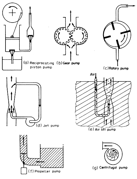
In a positive displacement pump, the fluid is drawn into the pump and
is then forced through the outlet. Types of positive displacement pumps
include: reciprocating piston pumps; gear pumps in which the fluid is
enmeshed in rotating gears and forced through the pump; rotary pumps in
which rotating vanes draw in and discharge fluid through a system of valves.
Positive displacement pumps can develop high-pressure heads but they cannot
tolerate throttling or blockages in the discharge. These types of pumps
are illustrated in Fig. 4.3 (a), (b) and (c).

Figure 4.3 Liquid pumps
Jet Pumps
In
jet pumps, a high-velocity jet is produced in a Venturi nozzle, converting
the energy of the fluid into velocity energy. This produces a low-pressure
area causing the surrounding fluid to be drawn into the throat as shown
diagrammatically in Fig. 4.3 (d) and the combined fluids are then
discharged. Jet pumps are used for difficult materials that cannot be
satisfactorily handled in a mechanical pump. They are also used as vacuum
pumps. Jet pumps have relatively low efficiencies but they have no moving
parts and therefore have a low initial cost. They can develop only low
heads per stage.
Air-lift Pumps
If air or gas is introduced into a liquid it can be used to impart energy
to the liquid as illustrated in Fig. 4.3 (e). The air or gas can
be either provided from external sources or produced by boiling within
the liquid. Examples of the air-lift principle are:
 Air
introduced into the fluid as shown in Fig. 4.3(e) to pump water from an
artesian well. Air
introduced into the fluid as shown in Fig. 4.3(e) to pump water from an
artesian well.
 Air
introduced above a liquid in a pressure vessel and the pressure used to
discharge the liquid. Air
introduced above a liquid in a pressure vessel and the pressure used to
discharge the liquid.
 Vapours
produced in the column of a climbing film evaporator. Vapours
produced in the column of a climbing film evaporator.
 In
the case of powdered solids, air blown up through a bed of powder to convey
it in a "fluidized" form. In
the case of powdered solids, air blown up through a bed of powder to convey
it in a "fluidized" form.
A
special case of this is in the evaporator, where boiling of the liquid
generates the gas (usually steam) and it is used to promote circulation.
Air or gas can be used directly to provide pressure to blow a liquid from
a container out to a region of lower pressure. Air-lift pumps and air
blowing are inefficient, but they are convenient for materials which will
not pass easily through the ports, valves and passages of other types
of pumps.
Propeller Pumps and Fan
Propellers can be used to impart energy to fluids as shown in Fig.
4.3 (f). They are used extensively to mix the contents of tanks
and in pipelines to mix and convey the fluid. Propeller fans are common
and have high efficiencies.
They
can only be used for low heads, in the case of fans only a few centimetres
or so of water.
Centrifugal Pumps and Fans
The centrifugal pump converts rotational energy
into velocity and pressure energy and is illustrated in Fig. 4.3(g).
The fluid to be pumped is taken in at the centre of a bladed rotor and
it then passes out along the spinning rotor, acquiring energy of rotation.
This rotational energy is then converted into velocity and pressure energy
at the periphery of the rotor. Centrifugal fans work on the same principles.
These machines are very extensively used and centrifugal pumps can develop
moderate heads of up to 20 m of water. They can deliver very large quantities
of fluids with high efficiency. The theory of the centrifugal pump is
rather complicated and will not be discussed. However, when considering
a pump for a given application, the manufacturers will generally supply
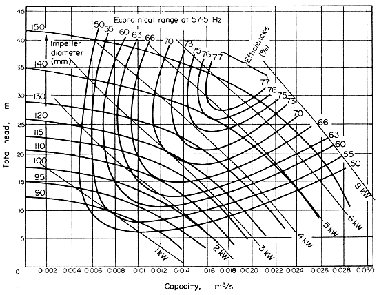
pump characteristic curves showing how the pump performs under
various conditions of loading. These curves should be studied in order
to match the pump to the duty required. Figure 4.4 shows
some characteristic curves for a family of centrifugal pumps.

Figure 4.4 Characteristic curves for centrifugal pumps
Adapted from Coulson and Richardson, Chemical Engineering,
2nd Edition, 1973.
For a given centrifugal pump, the capacity of the pump varies with its
rotational speed; the pressure developed by the pump varies as the square
of the rotational speed; and the power required by the pump varies as
the cube of the rotational speed. The same proportional relationships
apply to centrifugal fans and these relationships are often called the
"fan laws" in this context.
 EXAMPLE
4.3. Centrifugal pump for raising water EXAMPLE
4.3. Centrifugal pump for raising water
Water for a processing plant is required to be stored in a reservoir to
supply sufficient working head for washers. It is believed that a constant
supply of 1.2 m3 min-1 pumped to the reservoir,
which is 22 m above the water intake, would be sufficient. The length
of the pipe is about 120 m and there is available galvanized iron piping
15 cm diameter. The line would need to include eight right-angle bends.
There is available a range of centrifugal pumps whose characteristics
are shown in Fig. 4.4. Would one of these pumps be sufficient for the
duty and what size of electric drive motor would be required?
Assume properties
of water at 20°C are density 998 kg m-3, and viscosity
0.001 N s m-2
Cross-sectional
area of pipe A = (p/4)D2
= p/4
x (0.15)2
= 0.0177 m-2
Volume of flow V = 1.2 m3 min-1
= 1.2/60 m3 s-1
= 0.02 m3 s-1.
Velocity in the pipe = V/A
= (0.02)/(0.0177)
= 1.13 ms-1
Now (Re) = Dvr/m
= (0.15 x 1.13 x 998)/0.001
= 1.7 x 10⁵
and so the flow is clearly turbulent.
From Table 3.1, the
roughness factor e
is 0.0002 for galvanized iron
and so
roughness ratio e/D
= 0.0002/0.15 = 0.001
So from Fig. 3.8,
ƒ = 0.0053
Therefore the friction
loss of energy = (4ƒv2/2) x (L/D)
= [4ƒv2L/2D]
= [4 x 0.0053 x (1.13)2 x 120]/(2 x 0.15)
= 10.8 J.
For
the eight right-angled bends, from Table 3.2 we would expect a loss of
0.74 velocity energies at each, making (8 x 0.74) = 6 in all. There would
be one additional velocity energy loss because of the unrecovered flow
energy discharged into the reservoir.
velocity energy = v2/2
= (1.13)2/2
= 0.64 J
So total loss from bends and discharge energy
= (6 + 1) x 0.64
= 4.5 J
Energy to move 1 kg water against a head of 22 m of water is
E = Zg
= 22 x 9.81
= 215.8 J.
Total energy requirement
per kg:
Etot = 10.8 + 4.5 + 215.8
= 231.1 J
and theoretical power requirement
=
Energy x volume flow x density
= (Energy/kg) x kgs-1
= 231.1 x 0.02 x 998
= 4613 J s-1.
Now the head equivalent
to the energy requirement
= Etot/g
= 231.1/9.81
= 23.5 m of water,
 Back
to the top Back
to the top |
![]() Positive
Displacement Pumps
Positive
Displacement Pumps![]() Jet
pumps
Jet
pumps![]() Air-lift Pumps
Air-lift Pumps![]() Propeller Pumps
and Fan
Propeller Pumps
and Fan![]() Centrifugal Pumps
and Fans
Centrifugal Pumps
and Fans

