By suitable choice of sizes for the wire from which the sieves are woven,
the ratio of opening sizes has been kept approximately constant in moving
from one sieve to the next. Actually, the ratio of 2:1 is rather large
so that the normal series progresses in the ratio of Ö2:1
and if still closer ratios are required intermediate sieves are available
to make the ratio between adjacent sieves in the complete set 4Ö2
: 1.
The standard British series of sieves has been based on the available
standard wire sizes, so that, although apertures are generally of the
same order as the Tyler series, aperture ratios are not constant.
In the SI system, apertures are measured in mm. A table of sieve sizes
has been included in Appendix 10.
In
order to get reproducible results in accurate sieving work, it is necessary
to standardize the procedure. The analysis reports either the percentage
of material that is retained on each sieve, or the cumulative percentage
of the material larger than a given sieve size.
The
results of a sieve analysis can be presented in various forms, perhaps
the best being the cumulative analysis giving, as a function
of the sieve aperture (D), the weight fraction of the powder F(D) which
passes through that and larger sieves, irrespective of what happens on
the smaller ones. That is the cumulative fraction sums all particles smaller
than the particular sieve of interest.
Thus F
= F(D),
dF/dD = F ' (D)
where F '
(D) is the derivative of F(D) with respect to D.
So  dF
= dF
=  F
' (D) dD
(10.15) F
' (D) dD
(10.15)
and so integrating between D1 and D2 gives
the cumulative fraction between two sizes D2 (larger)
and D1 which is also that fraction passing through sieve
of aperture D2 and caught on that of aperture D1.
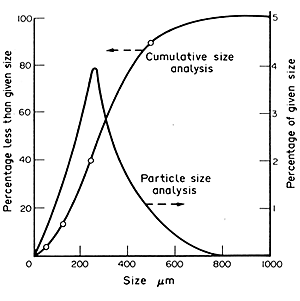
The F'(D) graph gives a particle size distribution analysis.
 EXAMPLE
10.7. Sieve analysis EXAMPLE
10.7. Sieve analysis
Given the following sieve analysis:
|
Sieve
size mm
|
%
Retained
|
|
1.00
|
0
|
|
0.50
|
11
|
|
0.25
|
49
|
|
0.125
|
28
|
|
0.063
|
8
|
|
Through
0.063
|
4
|
plot a cumulative
sieve analysis and estimate the weight fraction of particles of sizes
between 0.300 and 0.350 mm and 0.350 and 0.400 mm.
From
the above table:
| Less than
aperture (mm) |
63
|
125
|
250
|
500
|
1000
|
| Percentage
(cumulative) |
4
|
12
|
40
|
89
|
100
|
This has been plotted
on Fig. 10.9 and the graph F(D) has been
smoothed. From this the graph of F'(D) has been plotted,
working from that slope of F(D), to give the particle size
distribution.

FIG. 10.9 Particle-size analysis
To find the fraction between the specified sizes, eqn. (10.15) indicates
that this will be given directly by the fraction that the area under the
F ' (D) graph and between the sizes of interest is to the
total area under the
F' (D)
curve. Counting squares, on Fig. 10.9, gives:
between 0.300
and 0.350 mm as 13%
and
0.350 and 0.400 mm as 9%.
For
industrial sieving, it is seldom worthwhile to continue until equilibrium
is reached. In effect, a sieving-efficiency term is introduced, as a proportion
only of the particles smaller than a given size actually get through.
The sieves of a series are often mounted one above the other, and a mechanical
shaker used.
Sieve
analysis for particle-size determination should be treated with some caution
especially for particles deviating radically from spherical shape, and
it needs to be supplemented with microscopical examination of the powders.
The size distribution of powders can be useful to estimate parameters
of technological importance such as the surface area available for a reaction,
the ease of dispersion in water of a dried milk powder, or the performance
characteristics of a spray dryer or a separating cyclone.
Industrial
sieves include rotary screens, which are horizontal cylinders
either perforated or covered with a screen, into which the material is
fed. The smaller particles pass through as they tumble around in the rotating
screens. Other industrial sieves are vibrating screens, generally vibrated
by an eccentric weight; and multi-deck screens on which the particles
fall through from one screen to another, of decreasing apertures, until
they reach one which is too fine for them to pass. With vibrating screens,
the frequency and amplitude of the vibrations can significantly affect
the separation achieved. Screen capacities are usually rated in terms
of the quantity passed through per unit area in unit time. Particles that
can conveniently be screened industrially range from 50 mm
diameter, upwards.
Continuous
vibrating sieves used in the flour-milling industry employ a sieve of
increasing apertures as particles progress along the length of the screen.
So the finer fraction at any stage is being removed as the flour particles
move along. The shaking action of the sieve provides the necessary motion
to make the particles fall through and also conveys the oversize particles
on to the next section. Below the sieves, in some cases, air classification
may be used to remove bran.
 Mechanical
separations > SUMMARY, PROBLEMS Mechanical
separations > SUMMARY, PROBLEMS
 Back
to the top Back
to the top |
![]() nature and the shape of the particles,
nature and the shape of the particles, ![]() frequency and the amplitude of the shaking,
frequency and the amplitude of the shaking, ![]() methods used to prevent sticking or bridging of particles in the apertures
of the sieve and
methods used to prevent sticking or bridging of particles in the apertures
of the sieve and ![]() tension and physical nature of the sieve material.
tension and physical nature of the sieve material.
