Continuous-flow Heat Exchangers
It is very often convenient to use heat exchangers in which one or both
of the materials that are exchanging heat are fluids, flowing continuously
through the equipment and acquiring or giving up heat in passing.
One
of the fluids is usually passed through pipes or tubes, and the other
fluid stream is passed round or across these. At any point in the equipment,
the local temperature differences and the heat transfer coefficients
control the rate of heat exchange.
The
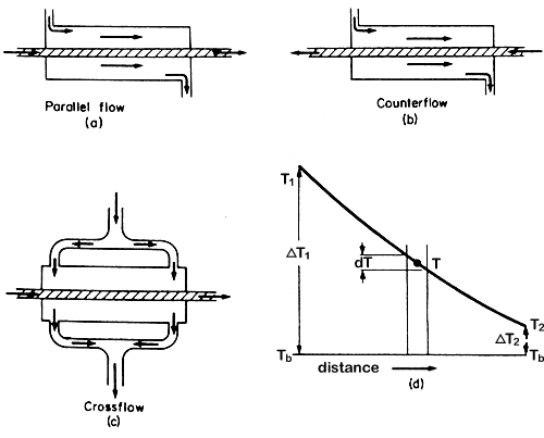
fluids can flow in the same direction through the equipment, this is called
parallel flow; they can flow in opposite directions, called counter
flow; they can flow at right angles to each other, called cross
flow. Various combinations of these directions of flow can occur
in different parts of the exchanger. Most actual heat exchangers of this
type have a mixed flow pattern, but it is often possible to treat them
from the point of view of the predominant flow pattern. Examples of these
exchangers are illustrated in Figure 6.1.

Figure 6.1 Heat exchangers
In parallel flow, at the entry to the heat exchanger, there is the maximum
temperature difference between the coldest and the hottest stream, but
at the exit the two streams can only approach each other's temperature.
In a counter flow exchanger, leaving streams can approach the temperatures
of the entering stream of the other component and so counter flow exchangers
are often preferred.
Applying the basic
overall heat-transfer equation for the the heat exchanger heat
transfer:
q = UA DT
uncertainty at once
arises as to the value to be chosen for DT,
even knowing the temperatures in the entering and leaving streams.
Consider
a heat exchanger in which one fluid is effectively at a constant temperature,
Tb as illustrated in Fig. 6.1(d). Constant temperature
in one component can result either from a very high flow rate of this
component compared with the other component, or from the component being
a vapour such as steam or ammonia condensing at a high rate, or from a
boiling liquid. The heat-transfer coefficients are assumed to be independent
of temperature.
The
rate of mass flow of the fluid that is changing temperature is G
kg s-1, its specific heat is cp J kg-1
°C-1. Over a small length of path of area dA, the
mean temperature of the fluid is T and the temperature drop is
dT. The constant temperature fluid has a temperature Tb.
The overall heat transfer coefficient is U J m-2 s-1 °C-1.
Therefore the heat
balance over the short length is:
cpGdT = U(T - Tb)dA
Therefore
U/)cpG) dA = dT/(T –Tb)
If this is integrated
over the length of the tube in which the area changes from A =
0 to A = A, and T changes from T1 to T2,
we have:
U/(cpG) A = ln[(T1 – Tb)/(T2
- Tb)] (where ln
= loge)
= ln (DT1/
DT2)
in which DT1
= (T1 – Tb) and DT2
= (T2 - Tb)
therefore cpG
= UA/ ln (DT1/
DT2)
From the overall
equation, the total heat transferred per unit time is given by
q = UADTm
where DTm
is the mean temperature difference, but the total heat transferred per
unit is also:
q = cpG(T1 –T2)
so q = UADTm
= cpG(T1 –T2)
= UA/ ln (DT1/
DT2)]
x (T1 –T2)
but (T1
–T2) can be written (T1 –
Tb) - (T2 - Tb)
so
(T1 –T2) = (DT1
- DT2)
therefore UADTm
= UA(DT1
- DT2)
/ ln (DT1/
DT2)
(6.1)
so
that
DTm =
(DT1
- DT2)
/ ln (DT1/
DT2)
(6.2)
where DTm
is called the log mean temperature difference.
In
other words, the rate of heat transfer can be calculated using the heat
transfer coefficient, the total area, and the log mean temperature difference.
This same result can be shown to hold for parallel flow and counter flow
heat exchangers in which both fluids change their temperatures.
The
analysis of cross-flow heat exchangers is not so simple, but for these
also the use of the log mean temperature difference gives a good approximation
to the actual conditions if one stream does not change very much in temperature.
 EXAMPLE
6.1. Cooling of milk in a pipe heat exchanger EXAMPLE
6.1. Cooling of milk in a pipe heat exchanger
Milk is flowing into a pipe cooler and passes through a tube of 2.5 cm
internal diameter at a rate of 0.4 kg s-1. Its initial temperature
is 49°C and it is wished to cool it to 18°C using a stirred bath
of constant 10°C water round the pipe. What length of pipe would be
required? Assume an overall coefficient of heat transfer from the bath
to the milk of 900 J m-2 s-1 °C-1,
and that the specific heat of milk is 3890 J kg-1 °C-1.
Now
q = cpG (T1 –T2)
= 3890 x 0.4 x (49 - 18)
= 48,240 J s-1
Also
q = UADTm
DTm
= [(49 - 10) - (18 –10)] / ln[(49 -10)1(18 - 10)]
= 19.6°C.
Therefore 48,240 = 900 x A x l9.6
A = 2.73 m2
but A = pDL
where L is the length of pipe of diameter D
Now D = 0.025 m.
L = 2.73/(p
x 0.025)
= 34.8 m
This
can be extended to the situation where there are two fluids flowing, one
the cooled fluid and the other the heated fluid. Working from the mass
flow rates (kg s-1) and the specific heats of the two fluids,
the terminal temperatures can normally be calculated and these can then
be used to determine DTm
and so, from the heat-transfer coefficients, the necessary heat-transfer
surface.
 EXAMPLE
6.2. Water chilling in a counter flow heat exchanger EXAMPLE
6.2. Water chilling in a counter flow heat exchanger
In a counter flow heat exchanger, water is being chilled by a sodium chloride
brine. If the rate of flow of the brine is 1.8 kg s-1 and that
of the water is 1.05 kg s-1, estimate the temperature to which
the water is cooled if the brine enters at -8°C and leaves at 10°C,
and if the water enters the exchanger at 32°C. If the area of the
heat-transfer surface of this exchanger is 55 m2, what is the
overall heat-transfer coefficient? Take the specific heats to be 3.38
and 4.18 kJ kg-1 °C-1 for the brine and the
water respectively.
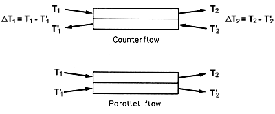
With heat exchangers a small sketch is often helpful:

Figure 6.2. Diagrammatic heat exchanger
Figure 6.2 shows three temperatures are known and the
fourth Tw2 (= T''2 say on Fig 6.2)
can be found from the heat balance:
By heat balance, heat loss in brine = heat gain in water
1.8 x 3.38 x [10
- (-8)] = 1.05 x 4.18 x (32 - Tw2)
Therefore
Tw2 = 7°C.
And for counterflow
DT1
= [32 - 10] = 22°C and DT2
= [7 - (-8)] = 15°C.
Therefore DTm
= (22 - 15)/ln(22/15)
=
7/0.382
= 18.3°C.
For the heat exchanger
q = heat exchanged between fluids = heat lost by brine = heat gain
to water
= heat passed across heat transfer surface
= UADTm
Therefore
3.38 x 1.8
x 18 = U x 55 x 18.3
U = 0.11 kJ m-2 °C-1
= 110
J m-2 °C-1
Parallel flow situations
can be worked out similarly, making appropriate adjustments.
In
some cases, heat-exchanger problems cannot be solved so easily; for example,
if the heat transfer coefficients have to be calculated from the basic
equations of heat transfer which depend on flow rates and temperatures
of the fluids, and the temperatures themselves depend on the heat-transfer
coefficients. The easiest way to proceed then is to make sensible estimates
and to go through the calculations. If the final results are coherent,
then the estimates were reasonable. If not, then make better estimates,
on the basis of the results, and go through a new set of calculations;
and if necessary repeat again until consistent results are obtained. For
those with multiple heat exchangers to design, computer programmes are
available.
Jacketed Pans
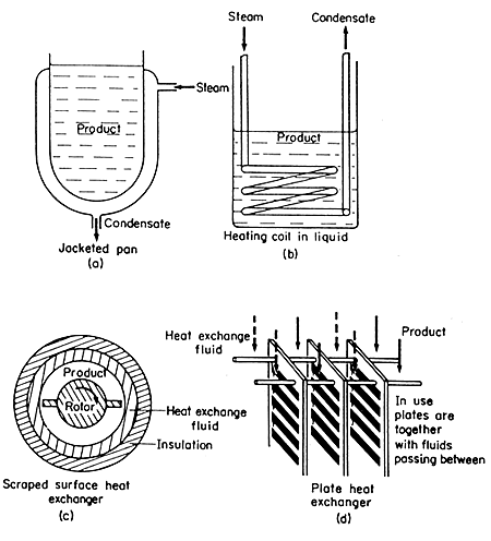
In
a jacketed pan, the liquid to be heated is contained in a vessel, which
may also be provided with an agitator to keep the liquid on the move across
the heat-transfer surface, as shown in Fig. 6.3(a).

Figure 6.3. Heat exchange equipment
The source of heat is commonly steam condensing in the vessel jacket.
Practical considerations of importance are:
1. There is the minimum of air with the steam in the jacket.
2. The steam is not superheated as part of the surface must then be used
as a de-superheater over which low gas heat-transfer coefficients apply
rather than high condensing coefficients.
3. Steam trapping to remove condensate and air is adequate.
The
action of the agitator and its ability to keep the fluid moved across
the heat transfer surface are important. Some overall heat transfer coefficients
are shown in Table 6.1. Save for boiling water, which
agitates itself, mechanical agitation is assumed. Where there is no agitation,
coefficients may be halved.
TABLE
6.1
SOME OVERALL HEAT TRANSFER COEFFICIENTS IN JACKETED PANS
|
Condensing
fluid
|
Heated
fluid
|
Pan
material
|
Heat
transfer coefficients
J m-2
s-1 °C-1
|
|
Steam
|
Thin
liquid
|
Cast-iron
|
1800
|
|
Steam
|
Thick
liquid
|
Cast-iron
|
900
|
|
Steam
|
Paste
|
Stainless
steel
|
300
|
|
Steam
|
Water,
boiling
|
Copper
|
1800
|
 EXAMPLE
6.3. Steam required to heat pea soup in jacketed pan EXAMPLE
6.3. Steam required to heat pea soup in jacketed pan
Estimate the steam requirement as you start to heat 50 kg of pea soup
in a jacketed pan, if the initial temperature of the soup is 18°C
and the steam used is at 100 kPa gauge. The pan has a heating surface
of 1 m2 and the overall heat transfer coefficient is assumed
to be 300 J m-2 s-1 °C-1.
From steam tables (Appendix 8), saturation
temperature of steam at 100 kPa gauge = 120°C and latent heat = l
= 2202 kJ kg-1.
q = UA DT
=
300 x 1 x (120 - 18)
= 3.06
x 104 J s-1
Therefore amount of steam
= q/l
= (3.06 x 10⁴)/(2.202 x 106)
= 1.4 x 10⁻²
kg s-1
= 1.4 x 10-2 x
3.6 x 103
= 50
kg h-1.
This
result applies only to the beginning of heating; as the temperature rises
less steam will be consumed as DT
decreases.
The overall heating process can be considered by using the analysis that
led up to eqn. (5.6). A stirred vessel to which heat enters from a heating
surface with a surface heat transfer coefficient which controls the heat
flow, follows the same heating or cooling path as does a solid body of
high internal heat conductivity with a defined surface heating area and
surface heat transfer coefficient.
 EXAMPLE
6.4. Time to heat pea soup in a jacketed pan EXAMPLE
6.4. Time to heat pea soup in a jacketed pan
In the heating of the pan in Example 6.3, estimate the time needed to
bring the stirred pea soup up to a temperature of 90°C, assuming the
specific heat is 3.95 kJ kg-1 °C-1.
From eqn.
(5.6) (T2 - Ta)/(T1–
Ta) = exp(-hsAt/crV
)
Ta = 120°C
(temperature of heating medium)
T1
= 18°C (initial soup temperature)
T2 = 90°C (soup temperature at end of time t)
hs
= 300 J m-2 s-1 °C-1
A = 1 m2,
c = 3.95 kJ kg-1 °C-1.
rV
= 50 kg
Therefore
t = -3.95 x 103
x 50 x ln (90 - 120) / (18 - 120)
300 x 1
= (-658)
x (-1.22) s
= 803 s
= 13.4 min.
Heating Coils Immersed in Liquids
In
some food processes, quick heating is required in the pan, for example,
in the boiling of jam. In this case, a helical coil may be fitted inside
the pan and steam admitted to the coil as shown in Fig. 6.3(b). This can
give greater heat transfer rates than jacketed pans, because there can
be a greater heat transfer surface and also the heat transfer coefficients
are higher for coils than for the pan walls. Examples of the overall heat
transfer coefficient U are quoted as:
 300-1400
for sugar and molasses solutions heated with steam using a copper coil, 300-1400
for sugar and molasses solutions heated with steam using a copper coil,
 1800
for milk in a coil heated with water outside, 1800
for milk in a coil heated with water outside,
 3600
for a boiling aqueous solution heated with steam in the coil. 3600
for a boiling aqueous solution heated with steam in the coil.
with the units in these coefficients being J m-2 s-1
°C-1.
Scraped Surface Heat Exchangers
One
type of heat exchanger, that finds considerable use in the food processing
industry particularly for products of higher viscosity, consists of a
jacketed cylinder with an internal cylinder concentric to the first and
fitted with scraper blades, as illustrated in Fig. 6.3(c). The blades
rotate, causing the fluid to flow through the annular space between the
cylinders with the outer heat transfer surface constantly scraped. Coefficients
of heat transfer vary with speeds of rotation but they are of the order
of 900-4000 J m-2 s-1 °C-1. These
machines are used in the freezing of ice cream and in the cooling of fats
during margarine manufacture.
Plate Heat Exchangers
A
popular heat exchanger for fluids of low viscosity, such as milk, is the
plate heat exchanger, where heating and cooling fluids flow through alternate
tortuous passages between vertical plates as illustrated in Fig. 6.3(d).
The plates are clamped together, separated by spacing gaskets, and the
heating and cooling fluids are arranged so that they flow between alternate
plates. Suitable gaskets and channels control the flow and allow parallel
or counter current flow in any desired number of passes. A substantial
advantage of this type of heat exchanger is that it offers a large transfer
surface that is readily accessible for cleaning. The banks of plates are
arranged so that they may be taken apart easily. Overall heat transfer
coefficients are of the order of 2400-6000 J m-2 s-1
°C-1.
 Heat-Transfer
Applications > THERMAL PROCESSING Heat-Transfer
Applications > THERMAL PROCESSING
 Back
to the top Back
to the top |
![]() Heat
exchangers
Heat
exchangers![]() Continuous-flow
Heat Exchangers
Continuous-flow
Heat Exchangers![]() Jacketed
Pans
Jacketed
Pans ![]() Heating
Coils Immersed in Liquids
Heating
Coils Immersed in Liquids ![]() Scraped
Surface Heat Exchangers
Scraped
Surface Heat Exchangers ![]() Plate
Heat Exchangers
Plate
Heat Exchangers 


