The
units of k, the thermal conductivity, can be found from eqn. (5.1)
by transposing the terms
k = dQ/dt
x 1/A x 1/(dT/dx)
=
J s-1 x m-2 x 1/(°C m-1)
= J m-1 s-1 °C-1
Equation (5.1) is
known as the Fourier equation for heat conduction.
Note:
Heat flows from a hotter to a colder body, that is in the direction of
the negative temperature gradient. Thus a minus sign should appear in
the Fourier equation. However, in simple problems the direction of heat
flow is obvious and the minus sign is considered to be confusing rather
than helpful, so it has not been used.
Thermal Conductivity
On the basis of eqn. (5.1) thermal conductivities of materials can be
measured. Thermal conductivity does change slightly with temperature,
but in many applications it can be regarded as a constant for a given
material. Thermal conductivities are given in Appendices 3,
4, 5, 6,
which give physical properties of many materials used in the food industry.
In
general, metals have a high thermal conductivity, in the region 50-400
J m-1 s-1 °C-1. Most foodstuffs contain
a high proportion of water and as the thermal conductivity of water is
about 0.7 J m-1 s-1°C-1 above 0°C,
thermal conductivities of foods are in the range 0.6 - 0.7 J m-1
s-1°C-1. Ice has a substantially higher thermal
conductivity than water, about 2.3 J m-1 s-1°C-1.
The thermal conductivity of frozen foods is, therefore, higher than foods
at normal temperatures.
Most
dense non-metallic materials have thermal conductivities of 0.5-2 J m-1
s-1°C-1. Insulating materials, such as those
used in walls of cold stores, approximate closely to the conductivity
of gases as they are made from non-metallic materials enclosing small
bubbles of gas or air. The conductivity of air is 0.024 J m-1
s-1 °C-1 at 0°C, and insulating materials
such as foamed plastics, cork and expanded rubber are in the range 0.03-
0.06 J m-1 s-1 °C-1. Some of the
new foamed plastic insulating materials have thermal conductivities as
low as 0.026 J m-1 s-1 °C-1.
When
using published tables of data, the units should be carefully checked.
Mixed units, convenient for particular applications, are sometimes used
and they may need to be converted.
Conduction
through a Slab
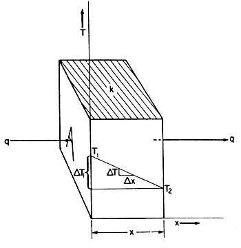
If a slab of material, as shown in Fig. 5.1, has two
faces at different temperatures T1 and T2
heat will flow from the face at the higher temperature T1
to the other face at the lower temperature T2.

Figure 5.1. Heat conduction through a slab
The rate of heat
transfer is given by Fourier's equation:
dQ/dt = kA DT/Dx
= kA dT/dx
Under steady temperature
conditions dQ/dt = constant, which may be called q:
and so q
= kA dT/dx
but
dT/dx, the rate of change of temperature per unit length
of path, is given by (T1 - T2)/x
where x is the thickness of the slab,
so q = kA(T1 - T2)/x
or q = kA DT/x
= (k/x) A DT
(5.2)
This
may be regarded as the basic equation for simple heat conduction. It can
be used to calculate the rate of heat transfer through a uniform wall
if the temperature difference across it and the thermal conductivity of
the wall material are known.
 EXAMPLE
5.1. Rate of heat transfer in cork EXAMPLE
5.1. Rate of heat transfer in cork
A cork slab 10 cm thick has one face at -12°C and the other face at
21°C. If the mean thermal conductivity of cork in this temperature
range is 0.042 J m-1 s-1 °C-1, what
is the rate of heat transfer through 1 m2 of wall?
 |
T1
= 21°C |
T2
= -12°C |
DT
= 33°C |
| |
A
= 1 m2 |
k
= 0.042 J m-1 s-1 °C-1 |
x = 0.1 m |
Heat
Conductances
In tables of properties of insulating materials, heat conductances are
sometimes used instead of thermal conductivities. The heat conductance
is the quantity of heat that will pass in unit time, through unit area
of a specified thickness of material, under unit temperature difference,
For a thickness x of material with a thermal conductivity of
k in J m-1 s-1 °C-1, the
conductance is k/x = C and the units of conductance
are
J m-2 s-1 °C-1.
Heat conductance
= C = k/x.
Heat Conductances in Series
Frequently in heat conduction, heat passes through several consecutive
layers of different materials. For example, in a cold store wall, heat
might pass through brick, plaster, wood and cork.
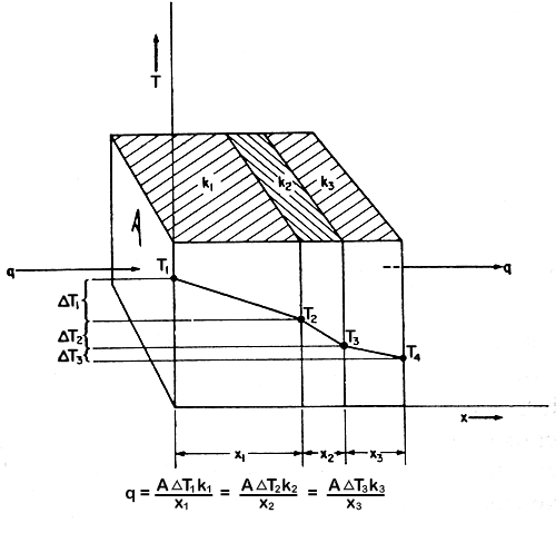
In this case, eqn.
(5.2) can be applied to each layer. This is illustrated in Fig.
5.2.

Figure 5.2 Heat conductances in series
In the steady state,
the same quantity of heat per unit time must pass through each layer.
q = A1DT1k1/x1
= A2DT2k2/x2
= A3DT3k3/x3
= ……..
If the areas are the same,
A1 = A2
= A3 = ….. = A
q = ADT1k1/x1
= ADT2k2/x2
= ADT3k3/x3
= ……..
So ADT1
= q(x1/k1) and ADT2
= q(x2/k2) and ADT3
= q(x3/k3).…..
ADT1
+ ADT2
+ ADT3
+ … = q(x1/k1)
+ q(x2/k2) +q(x3/k3)
+ …
A(DT1
+ DT2
+ DT3
+ ..) = q(x1/k1 + x2/k2
+x3/k3 + …)
The
sum of the temperature differences over each layer is equal to the difference
in temperature of the two outside surfaces of the complete system, i.e.
DT1
+ DT2
+ DT3
+ … = DT
and since k1/x1 is equal to the conductance of the
material in the first layer, C1, and k2/x2
is equal to the conductance of the material in the second layer C2,
x1/k1 + x2/k2
+ x3/k3 + ... = 1/C1
+ 1/C2 + 1/C3 ……
= 1/U
where U
= the overall conductance for the combined layers, in J m-2
s-1 °C-1
Therefore
ADT
= q(1/U)
And so
q = UADT
(5.3)
This
is of the same form as eqn (5.2) but extended to cover the composite slab.
U is called the overall heat-transfer coefficient, as it can also include
combinations involving the other methods of heat transfer – convection
and radiation.
 EXAMPLE
5.2. Heat transfer in cold store wall of brick, concrete and cork EXAMPLE
5.2. Heat transfer in cold store wall of brick, concrete and cork
A cold store has a wall comprising 11 cm of brick on the outside, then
7.5 cm of concrete and then 10 cm of cork. The mean temperature within
the store is maintained at -18°C and the mean temperature of the outside
surface of the wall is 18°C.
Calculate the rate of heat transfer through the wall. The appropriate
thermal conductivities are for brick, concrete and cork, respectively
0.69, 0.76 and 0.043 J m-1 s-1 °C-1.
Determine also the temperature at the interfaces between the concrete
and cork layers, and the brick and concrete layers.
For brick x1/k1
= 0.11/0.69 = 0.16.
For concrete x2/k2 = 0.075/0.76
= 0.10.
For cork x3/k3 =
0.10/0.043 = 2.33
.
But 1/U = x1/k1 + x2/k2
+ x3/k3
= 0.16 + 0.10 + 2.33
= 2.59
Therefore
U = 0.38 J m-2 s-1°C-1
DT
= 18 - (-18) = 36°C,
A = 1 m2
q = UADT
= 0.38 x 1 x 36
= 13.7 J
s-1
Further, q
= A3DT3k3/x3
and for the
cork wall A3 = 1 m2, x3/k3
= 2.33 and q = 13.7 J s-1
Therefore 13.7
= 1 x DT3
x 1/2.33 from
rearranging eqn. (5.2)
DT3
= 32°C.
But
DT3
is the difference between the temperature of the cork/concrete surface
Tc and the temperature of the cork surface inside the
cold store.
Therefore Tc
- (-18) = 32
where Tc
is the temperature at the cork/concrete surface
and so Tc = 14°C.
If DT1
is the difference between the temperature of the brick/concrete surface,
Tb, and the temperature of the external air.
Then 13.7
= 1 x DT1
x 1/ 0.16 = 6.25 DT1
Therefore 18
- Tb = DT1
= 13.7/6.25 = 2.2
so Tb
= 15.8 °C
Working it through
shows approximate boundary temperatures: air/brick 18°C,brick/concrete
16°C, concrete/cork 14°C, cork/air -18°C
This shows that almost
all of the temperature difference occurs across the insulation (cork):
and the actual intermediate temperatures can be significant especially
if they lie below the temperature at which the atmospheric air condenses,
or freezes.
Heat Conductances in Parallel
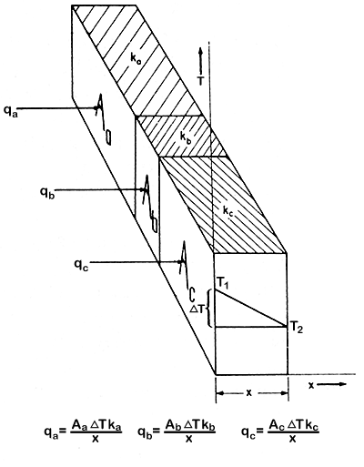
Heat conductances in parallel have a sandwich construction at right angles
to the direction of the heat transfer, but with heat conductances in parallel,
the material surfaces are parallel to the direction of heat transfer and
to each other. The heat is therefore passing through each material at
the same time, instead of through one material and then the next. This
is illustrated in Fig. 5.3..

Figure 5.3 Heat conductances in parallel
An example is the insulated wall of a refrigerator or an oven, in which
the walls are held together by bolts. The bolts are in parallel with the
direction of the heat transfer through the wall: they carry most of the
heat transferred and thus account for most of the losses.
 EXAMPLE
5.3. Heat transfer in walls of a bakery oven EXAMPLE
5.3. Heat transfer in walls of a bakery oven
The wall of a bakery oven is built of insulating brick 10 cm thick and
thermal conductivity 0.22 J m-1 s-1 °C-1.
Steel reinforcing members penetrate the brick, and their total area of
cross-section represents 1% of the inside wall area of the oven.
If the thermal conductivity of the steel is 45 J m-1 s-1
°C-1 calculate (a) the relative proportions of the total
heat transferred through the wall by the brick and by the steel and (b)
the heat loss for each m2 of oven wall if the inner side of
the wall is at 230°C and the outer side is at 25°C.
Applying
eqn. (5.1) q = ADTk/x,
we know that DT
is the same for the bricks and for the steel. Also x, the thickness,
is the same.
(a) Consider the
loss through an area of 1 m2 of wall (0.99 m2 of
brick, and 0.01 m2 of steel)
For brick qb = AbDT
kb/x
| = |
0.99(230
- 25)0.22
|
 |
 |
| |
0.10
|
| = |
446 J s-1 |
For steel qs
= AsDT
ks/x
| = |
0.01(230
- 25)45
|
 |
 |
| |
0.10
|
| = |
923 J s-1 |
Therefore qb
/qs = 0.48
(b) Total heat loss
q = (qb + qs ) per m2
of wall
= 446 + 923
= 1369 J s-1
Therefore percentage of heat carried by steel
= (923/1369) x 100
= 67%
 Heat-Transfer
Theory > SURFACE-HEAT TRANSFER Heat-Transfer
Theory > SURFACE-HEAT TRANSFER
 Back
to the top Back
to the top |
![]() Thermal
Conductivity
Thermal
Conductivity ![]() Conduction
through a Slab
Conduction
through a Slab![]() Heat
Conductances
Heat
Conductances ![]() Heat
Conductances in Series
Heat
Conductances in Series ![]() Heat
Conductances in Parallel
Heat
Conductances in Parallel 


