The
centrifugal force depends upon the radius and speed of rotation and upon
the mass of the particle. If the radius and the speed of rotation are
fixed, then the controlling factor is the weight of the particle so that
the heavier the particle the greater is the centrifugal force acting on
it. Consequently, if two liquids, one of which is twice as dense as the
other, are placed in a bowl and the bowl is rotated about a vertical axis
at high speed, the centrifugal force per unit volume will be twice as
great for the heavier liquid as for the lighter. The heavy liquid will
therefore move to occupy the annulus at the periphery of the bowl and
it will displace the lighter liquid towards the centre. This is the principle
of the centrifugal liquid separator, illustrated diagrammatically in Fig.
10.3.
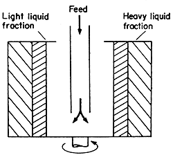
Figure 10.3 Liquid separation in a centrifuge
Rate of separation
The steady-state velocity of particles moving in a streamline flow under
the action of an accelerating force is, from eqn. (10.1),
vm = D2a(rp
- rf)
/18m
If a streamline flow
occurs in a centrifuge we can write, from eqns. (10.6) and (10.7) as a
is the tangential acceleration;:
Fc = ma
Fc/m = a = r(2pN/60)2
so that
vm = D2r(2pN/60)2(rp
- rf)
/18m
= D2N2r(rp
- rf)/1640m
(10.8)
 EXAMPLE
10.4. Centrifugal separation of oil in water
EXAMPLE
10.4. Centrifugal separation of oil in water
A dispersion of oil in water is to be separated using a centrifuge. Assume
that the oil is dispersed in the form of spherical globules 5.1 x 10⁻⁵
m diameter and that its density is 894 kg m-3. If the centrifuge
rotates at 1500 rev/min and the effective radius at which the separation
occurs is 3.8 cm, calculate the velocity of the oil through the water.
Take the density of water to be 1000 kg m-3 and its viscosity
to be
0.7 x 10⁻³
N s m-2. (The separation in this problem is the same as that
in Example 10.2, in which the
rate of settling under gravity was calculated.)
From eqn. (10.8)
vm = (5.1 x 10⁻⁵)2
x (1500)2 x 0.038 x (1000 - 894)/(1.64 x 103 x
0.7 x 10-3)
= 0.02 m s-1.
Checking that it
is reasonable to assume Stokes' Law
Re = (Dvr/m)
= (5.1 x 10-5
x 0.02 x 1000)/(7.0 x 10-4)
= 1.5
so that the flow is streamline and it should obey Stokes' Law.
Liquid Separation
The separation of one component of a liquid-liquid mixture, where the
liquids are immiscible but finely dispersed, as in an emulsion, is a common
operation in the food industry. It is particularly common in the dairy
industry in which the emulsion, milk, is separated by a centrifuge into
skim milk and cream. It seems worthwhile, on this account, to examine
the position of the two phases in the centrifuge as it operates. The milk
is fed continuously into the machine, which is generally a bowl rotating
about a vertical axis, and cream and skim milk come from the respective
discharges. At some point within the bowl there must be a surface of separation
between cream and the skim milk.
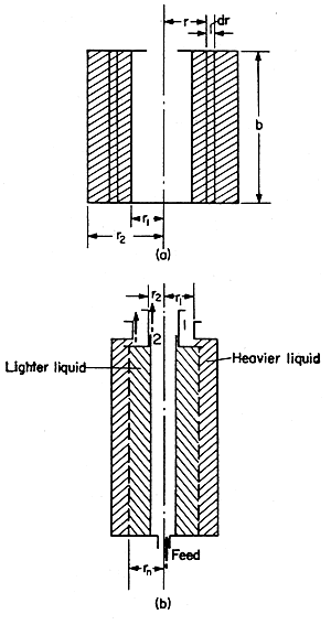
Figure 10.4 Liquid centrifuge (a) pressure difference (b) neutral zone
Consider a thin differential cylinder, of thickness dr and height
b as shown in Fig. 10.4(a): the differential centrifugal force
across the thickness dr is given by equation (10.5):
dFc = (dm)rw2
where
dFc is the differential force across the cylinder wall,
dm is the mass of the differential cylinder, w
is the angular velocity of the cylinder and r is the radius of
the cylinder. But,
dm = 2prrbdr
where r
is the density of the liquid and b is the height of the cylinder.
The area over which the force dFc acts is 2prb,
so that:
dFc
/2prb
= dP =rw2rdr
where dP is
the differential pressure across the wall of the differential cylinder.
To
find the differential pressure in a centrifuge, between radius r1
and r2, the equation for dP can be integrated,
letting the pressure at radius r1 be P1
and that at r2 be P2, and so
P2 - P1 = rw2
(r22 - r12)/2
(10.9)
Equation (10.9) shows
the radial variation in pressure across the centrifuge.
Consider
now Fig. 10.4(b), which represents the bowl of a vertical continuous liquid
centrifuge. The feed enters the centrifuge near to the axis, the heavier
liquid A discharges through the top opening 1 and the lighter liquid
B through the opening 2. Let r1 be the radius
at the discharge pipe for the heavier liquid and r2
that for the lighter liquid. At some other radius rn
there will be a separation between the two phases, the heavier and the
lighter. For the system to be in hydrostatic balance, the pressures of
each component at radius rn must be equal, so that applying
eqn. (10.9) to find the pressures of each component at radius rn,
and equating these we have:
rAw2
(rn2 - r12)/2
= rBw2(rn2–
r22)/2
rn2 =
(rAr12
- rBr22)
/ (rA
- rB)
(10.10)
where rA
is the density of the heavier liquid and rB
is the density of the lighter liquid.
Equation
(10.10) shows that as the discharge radius for the heavier liquid is made
smaller, then the radius of the neutral zone must also
decrease. When the neutral zone is nearer to the central axis, the lighter
component is exposed only to a relatively small centrifugal force compared
with the heavier liquid. This is applied where, as in the separation of
cream from milk, as much cream as possible is to be removed and the neutral
radius is therefore kept small. The feed to a centrifuge of this type
should be as nearly as possible into the neutral zone so that it will
enter with the least disturbance of the system. This relationship can,
therefore, be used to place the feed inlet and the product outlets in
the centrifuge to get maximum separation.
EXAMPLE
10.5. Centrifugal separation of milk and cream
If a cream separator has discharge radii of 5 cm and 7.5 cm and if the
density of skim milk is 1032 kg m-3 and that of cream is 915
kg m-3, calculate the radius of the neutral zone so that the
feed inlet can be designed.
For skim milk, r1 = 0.075m,
rA
= 1032 kg m-3, cream r2 = 0.05 m,
rB=
915 kg m-3
From eqn. (10.10)
rn2
= [1032 x (0.075)2 - 915 x (0.05)2] / (1032 -
915)
= 0.03 m2
rn = 0.17 m
=
17 cm
Centrifuge Equipment
The simplest form of centrifuge consists of a bowl spinning about a vertical
axis, as shown in Fig. 10.4(a). Liquids, or liquids and solids, are introduced
into this and under centrifugal force the heavier liquid or particles
pass to the outermost regions of the bowl, whilst the lighter components
move towards the centre.
If
the feed is all liquid, then suitable collection pipes can be arranged
to allow separation of the heavier and the lighter components. Various
arrangements are used to accomplish this collection effectively and with
a minimum of disturbance to the flow pattern in the machine. To understand
the function of these collection arrangements, it is very often helpful
to think of the centrifuge action as analogous to gravity settling, with
the various weirs and overflows acting in just the same way as in a settling
tank even though the centrifugal forces are very much greater than gravity.
In
liquid/liquid separation centrifuges, conical plates are arranged as illustrated
in Fig. 10.5(a) and these give smoother flow and better
separation.
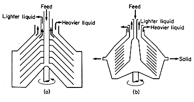
FIG. 10.5 Liquid centrifuges: (a) conical bowl, (b) nozzle
Whereas liquid phases can easily be removed from a centrifuge, solids
present much more of a problem.
In
liquid/solid separation, stationary ploughs cannot be used as these create
too much disturbance of the flow pattern on which the centrifuge depends
for its separation. One method of handling solids is to provide nozzles
on the circumference of the centrifuge bowl as illustrated in Fig. 10.5(b).
These nozzles may be opened at intervals to discharge accumulated solids
together with some of the heavy liquid. Alternatively, the nozzles may
be open continuously relying on their size and position to discharge the
solids with as little as possible of the heavier liquid. These machines
thus separate the feed into three streams, light liquid, heavy liquid
and solids, the solids carrying with them some of the heavy liquid as
well. Another method of handling solids from continuous feed is to employ
telescoping action in the bowl, sections of the bowl moving over one another
and conveying the solids that have accumulated towards the outlet, as
illustrated in Fig. 10.6(a).
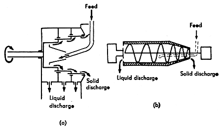
FIG. 10.6 Liquid/solid centrifuges (a) telescoping bowl, (b) horizontal
bowl, scroll discharge
The horizontal bowl with scroll discharge, centrifuge, as illustrated
in Fig.10.6(b) can discharge continuously. In this machine, the horizontal
collection scroll (or screw) rotates inside the conical-ended bowl of
the machine and conveys the solids with it, whilst the liquid discharges
over an overflow towards the centre of the machine and at the opposite
end to the solid discharge. The essential feature of these machines is
that the speed of the scroll, relative to the bowl, must not be great.
For example, if the bowl speed is 2000 rev/min, a suitable speed for the
scroll might be 25 rev/min relative to the bowl which would mean a scroll
speed of 2025 or 1975 rev/min. The differential speeds are maintained
by gearing between the driving shafts for the bowl and the scroll. These
machines can continuously handle feeds with solid contents of up to 30%.
A discussion of the action of centrifuges is given by Trowbridge
(1962) and they are also treated in McCabe
and Smith (1975) and Coulson and Richardson
(1977).
 Mechanical
separations > FILTRATION
Mechanical
separations > FILTRATION